A Validated Configuration Guide
Prelude
The content in this writing provides an implementation guide for the EdgeRouter ERPoe-5 and the Netgear GS108E to use in conjuntion with your F(iber) T(o) T(he) H(ome) (FTTH) connection to the I(nternet) S(ervice) P(rovider) XS4ALL. XS4ALL provides a Genexis device (NTU) to you as a customer giving you Ethernet connectivity to their PPoE server. The Genexis device is a C(ustomer) P(remises) E(quipment) (CPE) and by this is the property and responsibility of XS4ALL. Actually, the Genexis device consists of two parts, a F(iber) T(ermination) U(nit) (FTU) (passive) and a N(etwork) T(ermination) U(nit) (NTU) (active). The FTU faces the connection between your house and the fiber network while the NTU provides you with an Ethernet interface towards your domestic network appliances. The FTU part which provides a passive termination of the fiber connection between your home and the P(oint) O(f) P(resence), is in most cases not the property of your ISP but more likely the property of a larger Tier 2 ISP (e.g. KPN) or an intermediary connectivity provider. The Genexis NTU is an active network element providing VLAN trunking, QoS etc. In the XS4ALL setup, the Genexis NTU delivers a dot1q Layer 2 trunk (applying pleonasm here) with the VLANs 4 and 6. VLAN 4 is used for Multicast (IPTV) and VLAN 6 is used for Internet (PPPoE setup is required).
Requirements
VLAN4 and VLAN6 must be taken from the trunk between the NTU and the Netgear GS108E and put on dedicated switch ports. The Netgear GS108E must send Multicast traffic only downstream to the ports from which an IGMP join packet has been received. The Internet traffic must be handled by the EdgeRouter ERPoe-5 which must act as a PPPoE client and make a PPPoE connection to XS4ALL. The EdgeRouter ERPoe-5 must supply IP addresses, gateway and DNS data to hosts on the internal network. The EdgeRouter ERPoe-5 must provide Internet connectivity to devices on the internal network.
Considerations
Interfaces eth0 and eth1 of the EdgeRouter ERPoe-5 have each a Gig path
to the CPU. Only interfaces eth0 and eth1 can have traffic flow
hardware offloaded from the CPU. Interfaces eth2 through eth4 share a
single Gig bus.
As such, for optimum performance only interfaces eth0 and eth1 are being
used.
An EdgeRouter ERLite-3 is a better option for it gives you three routed
ports which can be (hardware) offloaded instead of only two offloaded
ports on the EdgeRouter ERPoe-5.
Trunk ports must have tagged VLANs and an Access port must have an untagged VLAN. For ingress traffic the Port VLAN ID (PVID) must be configured on the same port where the untagged VLAN has been configured. As such the VLAN tag is being applied when the packet is leaving the interface. This looks a little bit like the pop and tag on IOS XE.
Use the supplied configuration files and diagrams for they have proven to provide optimal results. If you want to change some settings to your own liking and you are not familiar with EdgeOS, then I advise you to change one item at a time and to test each time before doing the next change.
Feature Set Used
D(eep) P(acket) I(nspection) (DPI) is configured as well as a statefull firewall on the interface facing the W(ide) A(ccess) N(etwork) (WAN/ISP) network. An internal DHCP server is configured which listens and responds only on the relevant interface. An OpenVPN client is configured and tied to an ingress port by means of Policy Based Routing. N(etwork) A(ddress) T(ranslation) (NAT) is performed separately for the pppoe0 interface to the ISP as well as to the tun0 interface towards the OpenVPN server. In production the supplied configuration, used with the correct UTP cables (UTP 5e/6), can easily support the 500/500 mbit/s bandwidth provided by my ISP. Since the traffic is hardware offloaded, the CPU stays at about 3-6% when forwarding 512 mbit/s from the WAN/ISP to my internal network.
Planning
The first step is to plan how you are going to connect your devices to
your new network equipment. Below is an example. You can change the
ports on the Netgear GS108E as you like but be warned that you
can’t use other ports then the eth0 and the eth1 on the EdgeRouter
ERPoe-5 for those two ports are the only ports which support hardware
offloading for PPPoE/Forwarding/VLAN/IPSec traffic.
Connection Tables
Connnection Table EdgeRouter ERPoe-5- Eth0 (PPPoE)
<->Netgear port6 (Internet Upstream) - Eth1 (10.26.52.1) (Internal Network Gateway)
<->Netgear port2 - Eth4 (10.20.30.1/24)
<->ROKU Device (10.20.30.2/24)
- Eth0 (PPPoE)
Connection Table Netgear GS108E- Port1 - VLAN2 - Internal VLAN
<->QNAP NAS - Port2 - VLAN2 - Internal VLAN
<->EdgeRouter Eth1 - Port3 - VLAN2 - Internal VLAN
<->Asus RT-AC87U - Port4 - VLAN4 - IPTV
<->TV Set-Top Box - Port6 - VLAN6 - Internet
<->EdgeRouter Eth0 - Port8 - Trunk with VLAN 4 and 6
<->Genexis Switch
- Port1 - VLAN2 - Internal VLAN
Elaboration
- In order to comply with the requirements, the NTU connects to the Netgear GS108E which splits the Internet and Multicast traffic and only sends the Internet traffic to the EdgeRouter and only sends the Multicast / TV traffic to the TV Setupbox. The EdgeRouter acts as the upstream router for the different internal network segments. From the perspective of the Netgear switch the traffic to the EdgeRouter is Southbound whether the connection with the Genexis NTU device is Northbound.
- The Netgear GS108E receives the IP address 10.26.52.133/24 for its management interface.
- PPPoE is configured on Eth0 of the EdgeRouter. The EdgeRouter receives its global (Internet) IP address, DNS servers and default gateway from the ISP through the PPPoE connection.
- Eth4 on the EdgeRouter is tied with Policy Based Routing to an OpenVPN connection terminating in New York. The ROKU streaming device is connected to Eth4 and doesn’t know better than that it is located in New York.
- The ROKU device has a static IP address and has, through policy routing, its default gateway set to the tun0 interface. Routing through the tun0 interface is permissible since it is a point to point connection and thus has only one receiver on the other end.
- The traffic of the ROKU device is masqueraded behind the tun0 interface.
- DHCP services are provided through the Eth1 interface to the internal network and the IP address on this interface is functioning as the default gateway for the internal network. The internal addresses are masqueraded behind the global IP address acquired through the PPPoE connection on interface Eth0.
- The EdgeRouter does VPN, PPPoE and (policy based) routing.
- The TV Set-Top Box is connected directly to the Netgear switch.
- The NAS is connected on a dedicated port on the Netgear switch.
- The Wireless router is connected on a dedicated port on the Netgear switch.
NetGear GS108E Configuration
Following are the relevant screenshots for the needed configuration
NetGear VLAN Configuration
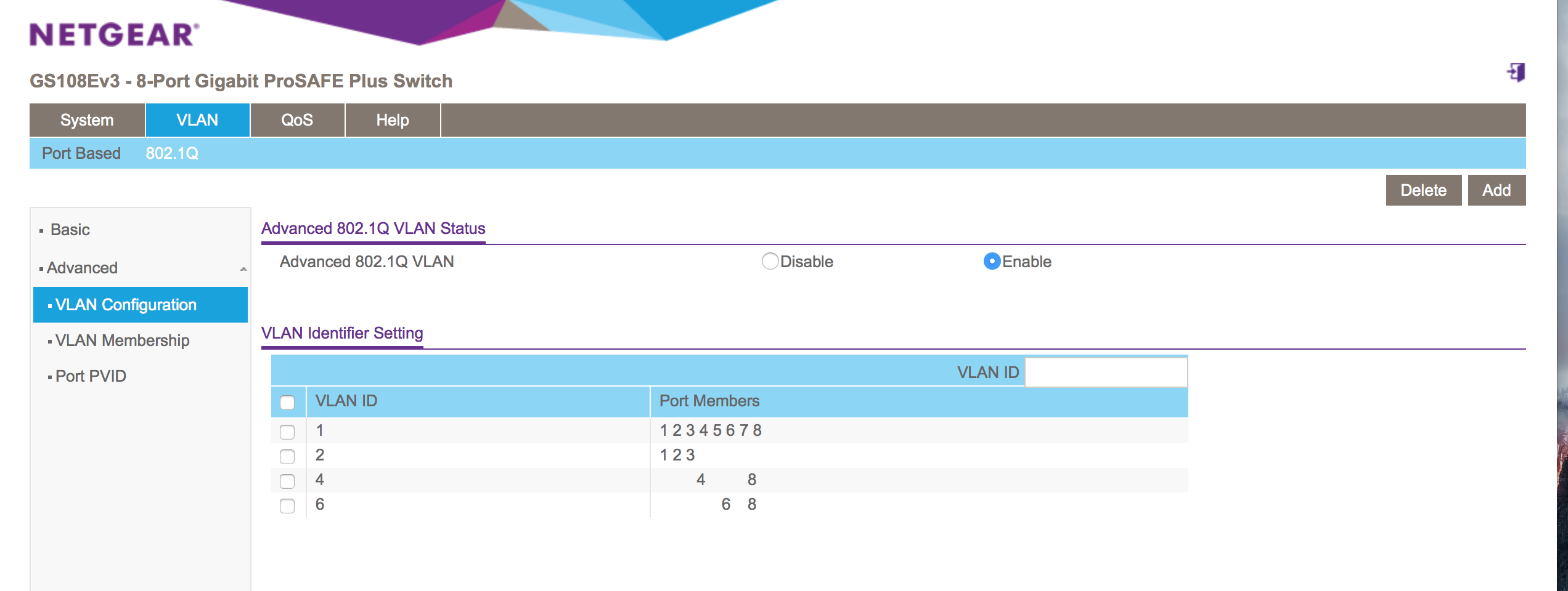
Figure 1
Netgear GS108E PVID Configuration
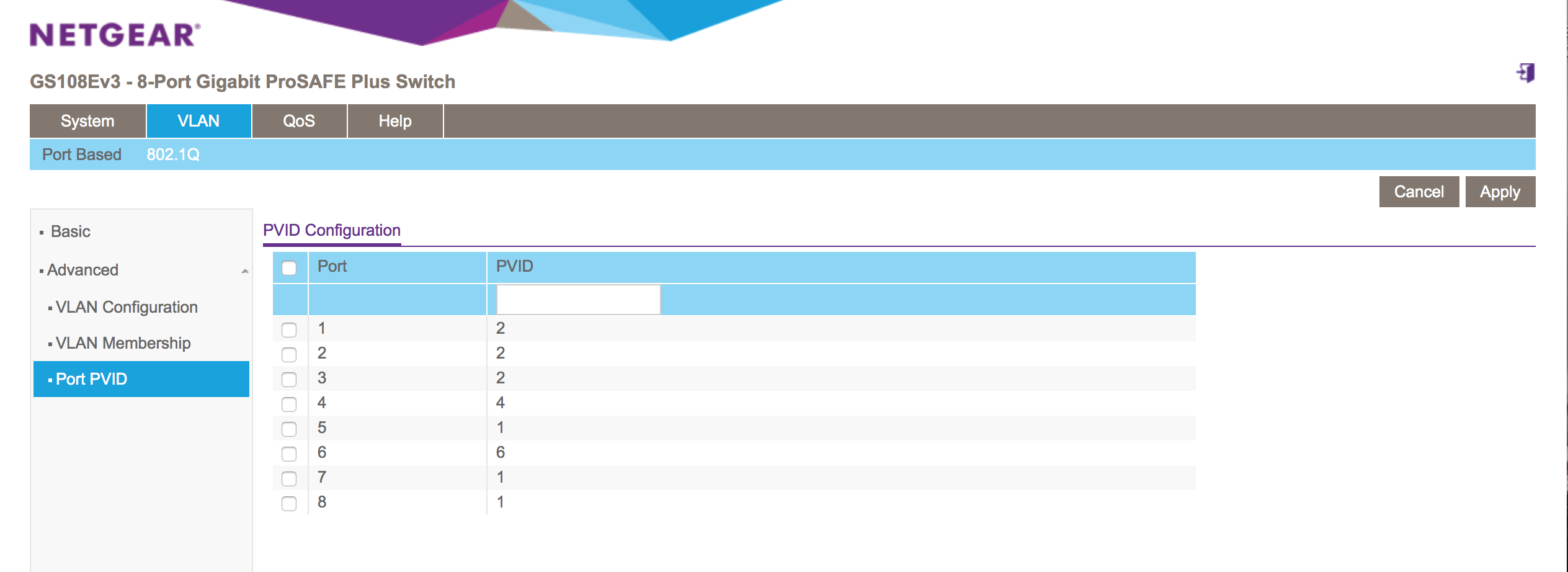
Figure 2
EdgeRouter ERPoe 5
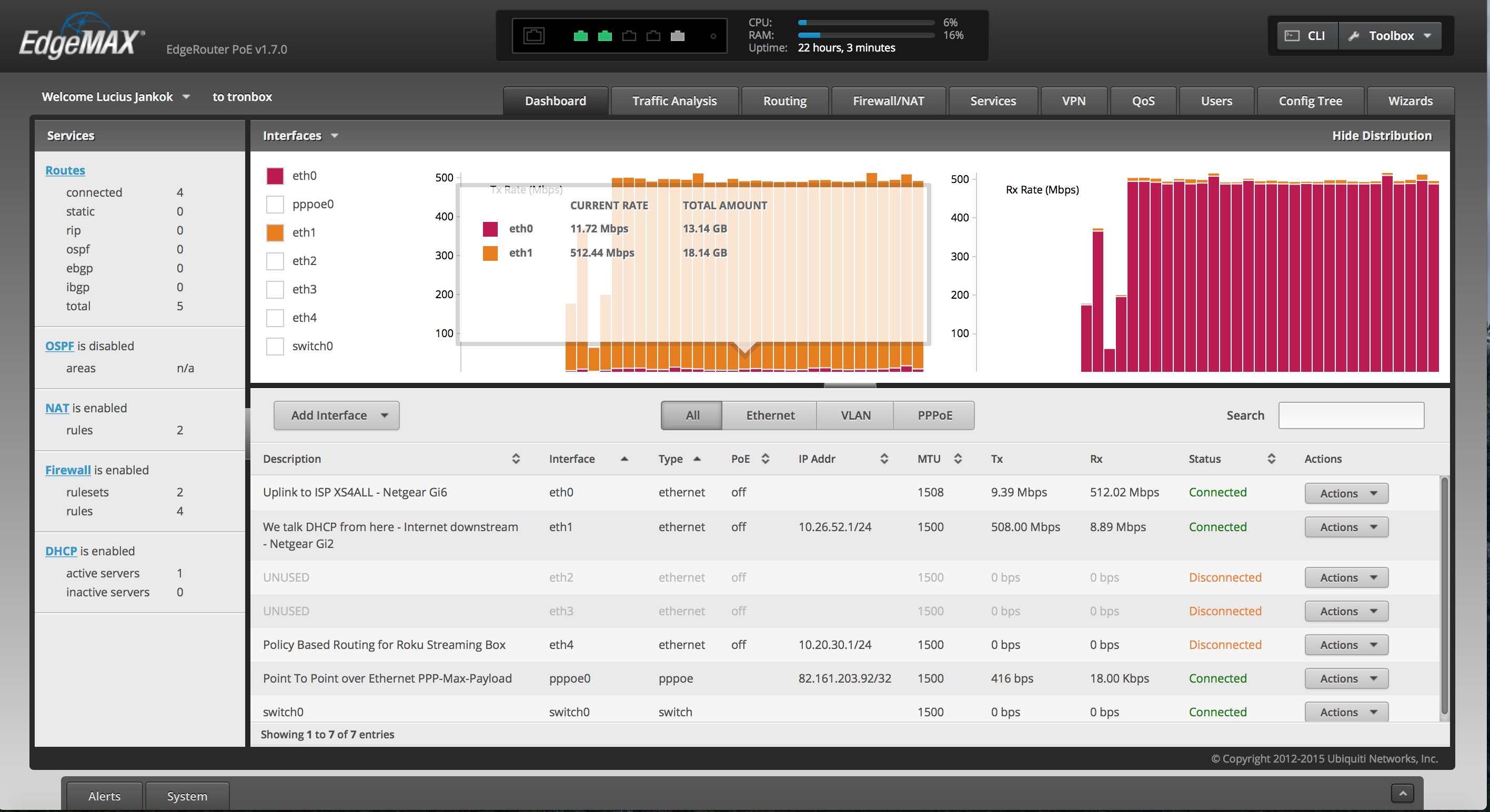
EdgeRouter Running Configuration
The ERPoe 5 router is configured with “set commands” although the config looks like it has been applied hierarchically on the command line. In a sense it is configured hierarchically but it doesn’t provide the hierachical configuration option provided by the IOS XR (or Juniper for that matter). The output however does have some resemblance with the IOS XR output.
Following is the running configuration for the EdgeRouter.
The translation back to “set commands” is quite easy to accomplish. Each indentation denotes a hierarchy. This is exactly the same as with the Cisco ASR routers running on IOS XR. To configure line 2 for instance would translate in the following set command:
set firewall all-ping enable
1. firewall {
2. all-ping enable
3. broadcast-ping disable
4. ipv6-receive-redirects disable
5. ipv6-src-route disable
6. ip-src-route disable
7. log-martians enable
8. modify ROKU_SOURCE {
9. description "Roku Streaming Device"
10. rule 10 {
11. action modify
12. modify {
13. table 1
14. }
15. source {
16. address 10.20.30.2/24
17. }
18. }
19. }
20. name wan_in {
21. default-action drop
22. description "Traffic from the Internet to Local Network"
23. enable-default-log
24. rule 1 {
25. action accept
26. state {
27. established enable
28. related enable
29. }
30. }
31. }
32. name wan_local {
33. default-action drop
34. description "Traffic from Internet to Backplane"
35. enable-default-log
36. rule 1 {
37. action accept
38. state {
39. established enable
40. related enable
41. }
42. }
43. rule 2 {
44. action drop
45. log enable
46. state {
47. invalid enable
48. }
49. }
50. rule 5 {
51. action accept
52. description "ICMP 50/m"
53. limit {
54. burst 1
55. rate 50/minute
56. }
57. log enable
58. protocol icmp
59. }
60. }
61. options {
62. }
63. receive-redirects disable
64. send-redirects enable
65. source-validation disable
66. syn-cookies enable
67. }
68. interfaces {
69. ethernet eth0 {
70. description "Uplink to ISP XS4ALL - Netgear Gi6"
71. duplex auto
72. mtu 1508
73. poe {
74. output off
75. }
76. pppoe 0 {
77. default-route auto
78. description "Point To Point over Ethernet PPP-Max-Payload"
79. firewall {
80. in {
81. name wan_in
82. }
83. local {
84. name wan_local
85. }
86. }
87. mtu 1500
88. name-server auto
89. password xs4all
90. user-id FB7490@xs4all.nl
91. }
92. speed auto
93. }
94. ethernet eth1 {
95. address 10.26.52.1/24
96. description "We talk DHCP from here - Internet downstream - Netgear Gi2"
97. duplex auto
98. mtu 1500
99. poe {
100. output off
101. }
102. speed auto
103. }
104. ethernet eth2 {
105. description UNUSED
106. disable
107. duplex auto
108. mtu 1500
109. poe {
110. output off
111. }
112. speed auto
113. }
114. ethernet eth3 {
115. description UNUSED
116. disable
117. duplex auto
118. mtu 1500
119. poe {
120. output off
121. }
122. speed auto
123. }
124. ethernet eth4 {
125. address 10.20.30.1/24
126. description "Policy Based Routing for Roku Streaming Box"
127. duplex auto
128. firewall {
129. in {
130. modify ROKU_SOURCE
131. }
132. }
133. mtu 1500
134. poe {
135. output off
136. }
137. speed auto
138. }
139. loopback lo {
140. }
141. switch switch0 {
142. mtu 1500
143. }
144. }
145. protocols {
146. static {
147. table 1 {
148. interface-route 0.0.0.0/0 {
149. next-hop-interface vtun0 {
150. }
151. }
152. }
153. }
154. }
155. service {
156. dhcp-server {
157. disabled false
158. hostfile-update enable
159. shared-network-name internal-network {
160. authoritative enable
161. description "Internal DHCP Server"
162. shared-network-parameters "DHCPDARGS=eth1;"
163. subnet 10.26.52.0/24 {
164. default-router 10.26.52.1
165. dns-server 194.109.6.66
166. dns-server 194.109.9.99
167. domain-name huize-familienaam.local
168. lease 86400
169. start 10.26.52.100 {
170. stop 10.26.52.150
171. }
172. }
173. }
174. }
175. gui {
176. https-port 443
177. }
178. nat {
179. rule 5000 {
180. description "Masquerade for pppoe0"
181. log disable
182. outbound-interface pppoe0
183. type masquerade
184. }
185. rule 5001 {
186. description "Masquerade for vtun0"
187. log disable
188. outbound-interface vtun0
189. type masquerade
190. }
191. }
192. ssh {
193. port 22
194. protocol-version v2
195. }
196. }
197. system {
198. config-management {
199. commit-revisions 20
200. }
201. conntrack {
202. expect-table-size 2048
203. hash-size 32768
204. table-size 262144
205. }
206. host-name tronbox
207. login {
208. user topgozer {
209. authentication {
210. encrypted-password $6$yqs56rcFeh/WxyGj/
211. plaintext-password ""
212. }
213. full-name "Lucius Jankok"
214. level admin
215. }
216. }
217. ntp {
218. server 0.ubnt.pool.ntp.org {
219. }
220. server 1.ubnt.pool.ntp.org {
221. }
222. server 2.ubnt.pool.ntp.org {
223. }
224. server 3.ubnt.pool.ntp.org {
225. }
226. }
227. offload {
228. ipsec disable
229. ipv4 {
230. forwarding enable
231. pppoe enable
232. vlan enable
233. }
234. ipv6 {
235. forwarding enable
236. pppoe enable
237. vlan disable
238. }
239. }
240. syslog {
241. global {
242. facility all {
243. level notice
244. }
245. facility protocols {
246. level debug
247. }
248. }
249. }
250. time-zone UTC
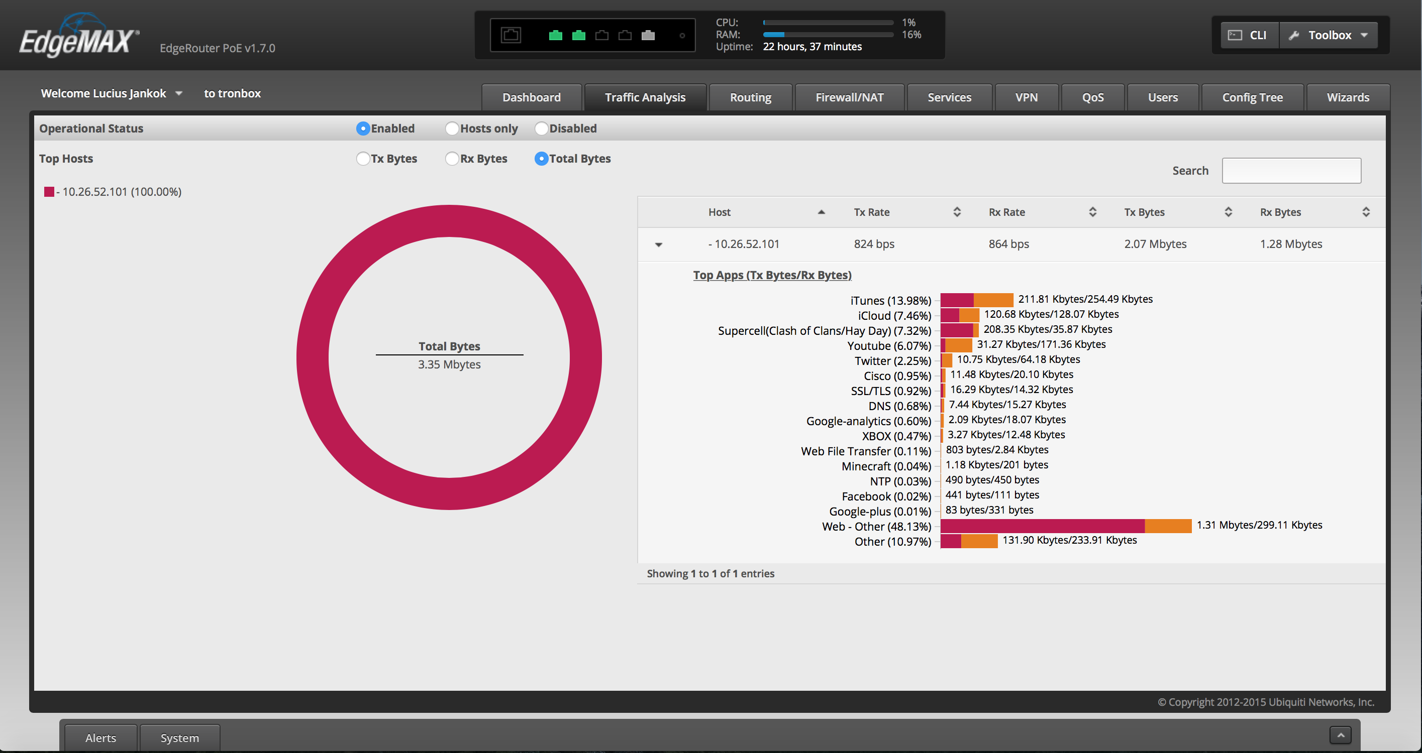
251. traffic-analysis {
252. dpi enable
253. export enable
254. }
255. }
OpenVPN Configuration Elaboration
The OpenVPN policy routing needs a bit more explanation. So here you have it. There are different ways to configure this. Since this is a home-scenario setup for providing Internet connectivity through our ISP, we don’t want to receive a default route from the OpenVPN Server.
Configure the OpenVPN Client
First we choose to override the default route (redirect-gateway) pushed by the OpenVPN server with the “route-nopull” option.
In the yourname.ovpn file we have the following:
client
[...]
route-nopull
Next we configure the OpenVPN client. Setting up an OpenVPN client on the EdgeOS is just too easy :) We put the configuration in the config partition such that it will survive a new firmware flash.
interfaces {
  [...]
  openvpn vtun0 {
    config-file /config/auth/openvpn/yourname.ovpn
  }
}
Configure Policy Routing
A policy route configuration consists of matching a particular traffic, defining a particular action on the matched traffic and lastly applying this combination (policy).
So first we need a way to match the traffic. Traffic matching is done through the firewall. So a firewall rule is defined to match the specific traffic.
Traffic Matching
1.  firewall {
[...]
8.      modify ROKU_SOURCE {
9.          description "Roku Streaming Device"
10.         rule 10 {
11.             action modify
12.             modify {
13.                 table 1
14.             }
15.             source {
16.                 address 10.20.30.2/24
17.             }
18.         }
19.     }
Action Definition
Next the action on the selection is done through the protocols configuration. In this case the matched traffic is given a default route through the vtun0 interface.
145.    protocols {
146.        static {
147.            table 1 {
148.                interface-route 0.0.0.0/0 {
149.                    next-hop-interface vtun0 {
150.                    }
151.                }
152.            }
153.        }
Apply Policy
Lastly we need to apply the match and action combo we defined. In this case we apply this to one specific interface.
interfaces {
[...]
124.        ethernet eth4 {
125.            address 10.20.30.1/24
126.            description "Policy Based Routing for Roku Streaming Box"
127.            duplex auto
128.            firewall {
129.                in {
130.                    modify ROKU_SOURCE
131.                }
132.            }
133.            mtu 1500
134.            poe {
135.                output off
136.            }
137.            speed auto
138.        }
Apply NAT/Masquerading
Don’t forget to hide the IP address of the ROKU device behind the IP address assigned to the vtun0 interface.
nat {
[...]
185.            rule 5001 {
186.                description "Masquerade for vtun0"
187.                log disable
188.                outbound-interface vtun0
189.                type masquerade
190.            }
And viola we are done. The match and action combo can be a lot of things. In this example we have matched on a specific IP and configure the action to apply a default gateway to it. There are many more possibilities off course.
Comments
So what do you think? Did I miss something? Is any part unclear? Leave your comment below.